extensions - finger jointed boxes
CNC controlled laser cutters have enabled the creation of inexpensive finger jointed boxes constructed from many materials. However, the creation of the patterns to feed into the laser can be quite time consuming. The finger jointed boxes methods within the cq_warehouse extensions package allow the creation of these patterns from a simple solid object.
Usage
To create these boxes, one just needs to create the solid object, select edges, and use the
makeFingerJoints() method, as follows:
import cadquery as cq
import cq_warehouse.extensions

# Create an empty assembly which will be populated with the finger jointed box
polygon_box_assembly = cq.Assembly()

# Create the box shape and then the finger jointed faces
polygon_box_faces = (
    cq.Workplane("XY")
    .polygon(5, 100)
    .extrude(60)
    .edges("not >Z")
    .makeFingerJoints(
        materialThickness=5,
        targetFingerWidth=20,
        kerfWidth=0,
        baseAssembly=polygon_box_assembly,
    )
)
# Is the finger jointed box valid?
print(f"{polygon_box_assembly.areObjectsValid()=}")
print(f"{polygon_box_assembly.doObjectsIntersect()=}")

# Store the faces as DXF files
for i, box_face in enumerate(polygon_box_faces.faces().vals()):
    center = box_face.Center()
    face_plane = cq.Plane(origin=center, normal=box_face.normalAt(center))
    face_workplane = cq.Workplane(face_plane).add(box_face)
    cq.exporters.export(face_workplane, fname="box_face" + str(i) + ".DXF")

if "show_object" in locals():
    show_object(polygon_box_assembly, name="polygon_box_assembly")
>>> polygon_box_assembly.areObjectsValid()
True
>>> polygon_box_assembly.doObjectsIntersect()
False
Warning
Not all shapes will result in a valid set of finger jointed box patterns.
Although the goal of this package is to enable the creation of a finger jointed box from any object with planar faces, this goal has not been fully achieved. Carefully inspect the output to ensure it is correct before cutting boxes to avoid disappointment.
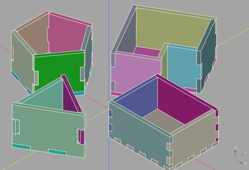
The Workplane used to create a finger jointed box must contain a solid object (actually a Solid or Compound object), and one or more Edges that is to be jointed. In the above example, all of the edges are selected except for those on the top of the object which results in an open box. The resulting faces can be further modified if required.
Here is an example of finger jointed faces of a simple box:
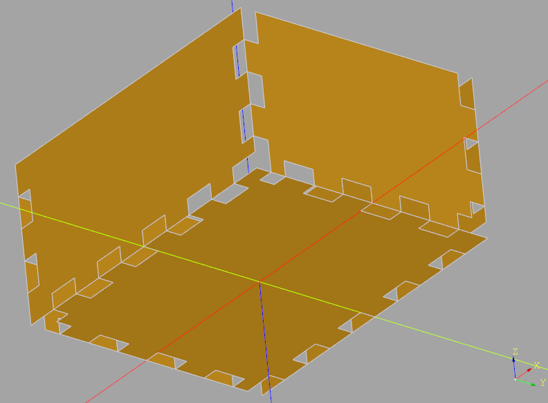
Notice how the finger joints on the nearest corner are in a different pattern than the simple fingers on the other parts of the box? This is done to avoid the creation of a missing corner.
Finger joint size is calculated internally such that an integer number of finger joints
are present on each edge - i.e. if the targetFingerWidth would result in a partial
finger joint, the actual finger joint width will reduced such the number of finger
joints is rounded to an integer. This may result in finger joints on different
edges being different sizes.
The use of an Assembly is optional but is recommended to aid in the visual validation of the output. Random colors are assigned to each of the box walls to aid this validation. Corners are where errors are most likely to appear, either as interference or as missing corners.
When working with shapes with non perpendicular faces (i.e. faces that don’t meet at 90˚) the depth of the finger joint is calculated to compensate for the angle by either making the joint extra deep (for angles greater than 90˚) or smaller (for angles less than 90˚). Unfortunately, not all possible combinations of corner angles have been compensated for so pay extra care when inspecting these corners.
The result of the makeFingerJoints() method is a set of
Faces within the Workplane aligned with the original solid object. To store these faces
as DXF files it is necessary to create a workplane oriented in the same way as the face
as shown in the above example.
The full API is as follows:
- Workplane.makeFingerJoints(materialThickness, targetFingerWidth, kerfWidth=0.0, baseAssembly=None)
Starting with a base object and a set of selected edges, create Faces with finger joints that they could be laser cut from flat material.
Example
For example, make a simple open topped laser cut box.
finger_jointed_box_assembly = Assembly()
finger_jointed_faces = (
    Workplane("XY")
    .box(100, 80, 60)
    .edges("not >Z")
    .makeFingerJoints(
        materialThickness=5,
        targetFingerWidth=10,
        kerfWidth=1,
        baseAssembly=finger_jointed_box_assembly,
    )
)
The assembly part is optional but if present the Assembly will contain the parts as if they were laser cut from a material of the given thickness.
- Parameters
self (T) – workplane
materialThickness (float) – thickness of finger joints
targetFingerWidth (float) – approximate with of notch - actual finger width will be calculated such that there are an integer number of fingers on Edge
kerfWidth (float, optional) – Extra size to add (or subtract) to account for the kerf of the laser cutter. Defaults to 0.0.
baseAssembly (Assembly, optional) – Assembly to add parts to
- Raises
ValueError – Missing Solid object
ValueError – Missing finger joint Edges
- Returns
Faces ready to be exported to DXF files and laser cut
- Return type
T
The kerfWidth parameter can be used to compensate for the size of the laser cut
thus allowing a path for the laser to the created directly from the face. Check with
the manufacturer to see if this compensation is required.
Validation
To help validate the finger jointed box two Assembly methods are available:
Checking for intersecting objects within the Assembly (a general purpose method where every
pair of objects within the Assembly - in their given Location - are checked for an intersection)
will identify if there are overlapping finger joints but will not find missing fingers. To check
for missing corners, one can use the Volume method as follows:
import cadquery as cq
import cq_warehouse.extensions

simple_box_assembly = Assembly()
simple_box = Workplane("XY").box(100, 80, 50)
simple_box_volume = simple_box.faces(">Z").shell(-5, kind="intersection").val().Volume()
simple_box_faces = (
    simple_box.edges("not >Z").makeFingerJoints(
        materialThickness=5,
        targetFingerWidth=10,
        baseAssembly=simple_box_assembly,
    )
)
simple_box_assembly_volume_error = abs(
    simple_box_assembly.toCompound().Volume() - simple_box_volume
)
print(f"Is volume correct: {simple_box_assembly_volume_error<1e-5=}")