extensions - CadQuery core enhancements
This python module provides extensions to the native CadQuery code base. Hopefully future generations of CadQuery will incorporate this or similar functionality.
Examples illustrating how to use much of the functionality of this sub-package can be found in the examples directory.
To help the user in debugging exceptions generated by the Opencascade core, the
dreaded StdFail_NotDone exception is caught and augmented with a more
meaningful exception where possible (a new exception is raised from
StdFail_NotDone so no information is lost). In addition, python logging is used
internally which can be enabled (currently by un-commenting the logging
configuration code) to provide run-time information in a cq_warehouse.log
file.
CadQuery Integration
In order for cq_warehouse CadQuery extensions to be recognized by IDEs (e.g. Intellisense) the CadQuery source code needs to be updated. Although monkeypatching allows for the functionality of CadQuery to be extended, these extensions are not visible to the IDE which makes working with them more difficult.
The build_cadquery_patch.py
script takes the cq_warehouse extensions.py file (from your pip install) and generates a patch file
custom to the version of CadQuery that you’re using (the version found with the python import cadquery).
The user needs to apply the patch for the changes to take effect. Reversing the patch will restore the changed
files. The patch command can also generate versioned backups of the changed files if
the user wants even more security.
Currently, cq_warehouse.extensions augments these CadQuery source files:
assembly.py,
cq.py,
geom.py,
shapes.py, and
sketch.py.
Usage:
>>> python build_cadquery_patch.py
To apply the patch:
    cd /home/gumyr/anaconda3/envs/cadquery-dev/lib/python3.9/site-packages/cadquery
    patch -s -p4 < cadquery_extensions0.5.2.patch
To reverse the patch:
    patch -R -p4 < cadquery_extensions0.5.2.patch
Warning
This script is designed to work on all platforms that support the diff and patch
commands but has only been tested on Ubuntu Linux.
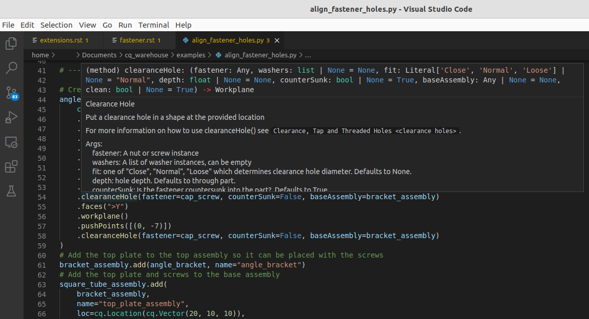
Once the patch has been applied, IDE’s like Visual Studio Code will see all the cq_warehouse extensions as native CadQuery functionality and will show all the type hints and code completion available with core CadQuery methods. It will look something like this:
Functions
- makeNonPlanarFace(exterior, surfacePoints=None, interiorWires=None)
Create Non-Planar Face
Create a potentially non-planar face bounded by exterior (wire or edges), optionally refined by surfacePoints with optional holes defined by interiorWires.
- Parameters
exterior (
Union[Wire,list[Edge]]) – Perimeter of facesurfacePoints (
Optional[list[VectorLike]]) – Points on the surface that refine the shape. Defaults to None.interiorWires (
Optional[list[Wire]]) – Hole(s) in the face. Defaults to None.
- Raises
RuntimeError – Opencascade core exceptions building face
- Return type
- Returns
Non planar face
Assembly class extensions
- class Assembly
- areObjectsValid()
Are Objects Valid
Check the validity of all the objects in this Assembly
- Returns
all objects are valid
- Return type
bool
- doObjectsIntersect(tolerance=1e-05)
Do Objects Intersect
Determine if any of the objects within an Assembly intersect by intersecting each of the shapes with each other and checking for a common volume.
- Parameters
self (Assembly) – Assembly to test
tolerance (float, optional) – maximum allowable volume difference. Defaults to 1e-5.
- Returns
do the object intersect
- Return type
bool
- fastenerLocations(fastener)
Return location(s) of fastener
Generate a list of cadquery Locations for the given fastener relative to the Assembly
- fastenerQuantities(bom=True, deep=True)
Fastener Quantities
Generate a bill of materials of the fasteners in an assembly augmented by the hole methods bom: returns fastener.info if True else counts fastener instances
- Parameters
bom (bool, optional) – Select a Bill of Materials or raw fastener instance count. Defaults to True.
deep (bool, optional) – Scan the entire Assembly. Defaults to True.
- Return type
dict- Returns
fastener usage summary
- findLocation(target)
Find Location of named target
Return the Location of the target object relative to the given Assembly including the given Assembly.
- Parameters
target (str) – name of target object
- Raises
ValueError – target object not in found in Assembly
- Returns
Location of target relative to self
- Return type
cq.Location
- rotate(axis, angle)
Rotate Assembly
Rotates the current assembly (without making a copy) around the axis of rotation by the specified angle
- Parameters
axis (
VectorLike) – The axis of rotation (starting at the origin)angle (
float) – The rotation angle, in degrees
- Return type
- Returns
The rotated Assembly
Example
car_assembly.rotate((0,0,1),90)
- section(plane)
Cross Section
Generate a 2D slice of an assembly as a colorize Assembly
Edge class extensions
- class Edge
- distributeLocations(count, start=0.0, stop=1.0, positions_only=False)
Distribute Locations
Distribute locations along edge or wire.
- Parameters
count (int) – Number of locations to generate
start (float, optional) – position along Edge|Wire to start. Defaults to 0.0.
stop (float, optional) – position along Edge|Wire to end. Defaults to 1.0.
positions_only (bool, optional) – only generate position not orientation. Defaults to False.
- Raises
ValueError – count must be two or greater
- Returns
locations distributed along Edge|Wire
- Return type
list[Location]
- embossToShape(targetObject, surfacePoint, surfaceXDirection, tolerance=0.01)
Emboss Edge on target object
Emboss an Edge on the XY plane onto a Shape while maintaining original edge dimensions where possible.
- Parameters
targetObject (
Shape) – Object to emboss ontosurfacePoint (
VectorLike) – Point on target object to start embossingsurfaceXDirection (
VectorLike) – Direction of X-Axis on target objecttolerance (
float) – maximum allowed error in embossed edge length
- Return type
- Returns
Embossed edge
- projectToShape(targetObject, direction=None, center=None)
Project Edge
Project an Edge onto a Shape generating new Wires on the surfaces of the object one and only one of direction or center must be provided. Note that one or more wires may be generated depending on the topology of the target object and location/direction of projection.
To avoid flipping the normal of a face built with the projected wire the orientation of the output wires are forced to be the same as self.
- Parameters
targetObject (
Shape) – Object to project ontodirection (
Optional[VectorLike]) – Parallel projection direction. Defaults to None.center (
Optional[VectorLike]) – Conical center of projection. Defaults to None.
- Raises
ValueError – Only one of direction or center must be provided
- Return type
list[Edge]- Returns
Projected Edge(s)
Face class extensions
- class Face
- embossToShape(targetObject, surfacePoint, surfaceXDirection, internalFacePoints=None, tolerance=0.01)
Emboss Face on target object
Emboss a Face on the XY plane onto a Shape while maintaining original face dimensions where possible.
Unlike projection, a single Face is returned. The internalFacePoints parameter works as with projection.
- Parameters
targetObject (
Shape) – Object to emboss ontosurfacePoint (
VectorLike) – Point on target object to start embossingsurfaceXDirection (
VectorLike) – Direction of X-Axis on target objectinternalFacePoints (
Optional[list[Vector]]) – Surface refinement points. Defaults to None.tolerance (
float) – maximum allowed error in embossed wire length. Defaults to 0.01.
- Returns
Embossed face
- Return type
- isInside(point, tolerance=1e-06)
Point inside Face
Returns whether or not the point is inside a Face within the specified tolerance. Points on the edge of the Face are considered inside.
- Parameters
point (VectorLike) – tuple or Vector representing 3D point to be tested
tolerance (float, optional) – tolerance for inside determination. Defaults to 1.0e-6.
- Returns
indicating whether or not point is within Face
- Return type
bool
- makeFingerJoints(fingerJointEdge, fingerDepth, targetFingerWidth, cornerFaceCounter, openInternalVertices, alignToBottom=True, externalCorner=True, faceIndex=0)
Given a Face and an Edge, create finger joints by cutting notches.
- Parameters
self (Face) – Face to modify
fingerJointEdge (Edge) – Edge of Face to modify
fingerDepth (float) – thickness of the notch from edge
targetFingerWidth (float) – approximate with of notch - actual finger width will be calculated such that there are an integer number of fingers on Edge
cornerFaceCounter (dict) – the set of faces associated with every corner
openInternalVertices (dict) – is a vertex part an opening?
alignToBottom (bool, optional) – start with a finger or notch. Defaults to True.
externalCorner (bool, optional) – cut from external corners, add to internal corners. Defaults to True.
faceIndex (int, optional) – the index of the current face. Defaults to 0.
- Returns
the Face with notches on one edge
- Return type
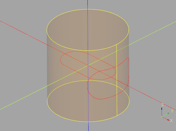
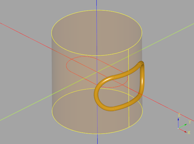
- makeHoles(interiorWires)
Make Holes in Face
Create holes in the Face ‘self’ from interiorWires which must be entirely interior. Note that making holes in Faces is more efficient than using boolean operations with solid object. Also note that OCCT core may fail unless the orientation of the wire is correct - use
cq.Wire(forward_wire.wrapped.Reversed())to reverse a wire.Example
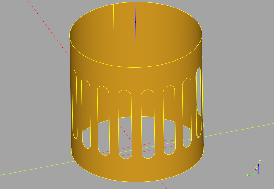
For example, make a series of slots on the curved walls of a cylinder.
cylinder = cq.Workplane("XY").cylinder(100, 50, centered=(True, True, False))
cylinder_wall = cylinder.faces("not %Plane").val()
path = cylinder.section(50).edges().val()
slot_wire = cq.Workplane("XY").slot2D(60, 10, angle=90).wires().val()
embossed_slot_wire = slot_wire.embossToShape(
    targetObject=cylinder.val(),
    surfacePoint=path.positionAt(0),
    surfaceXDirection=path.tangentAt(0),
)
embossed_slot_wires = [
    embossed_slot_wire.rotate((0, 0, 0), (0, 0, 1), a) for a in range(90, 271, 20)
]
cylinder_wall_with_holes = cylinder_wall.makeHoles(embossed_slot_wires)
- Parameters
interiorWires (
list[Wire]) – a list of hole outline wires- Raises
RuntimeError – adding interior hole in non-planar face with provided interiorWires
RuntimeError – resulting face is not valid
- Returns
‘self’ with holes
- Return type
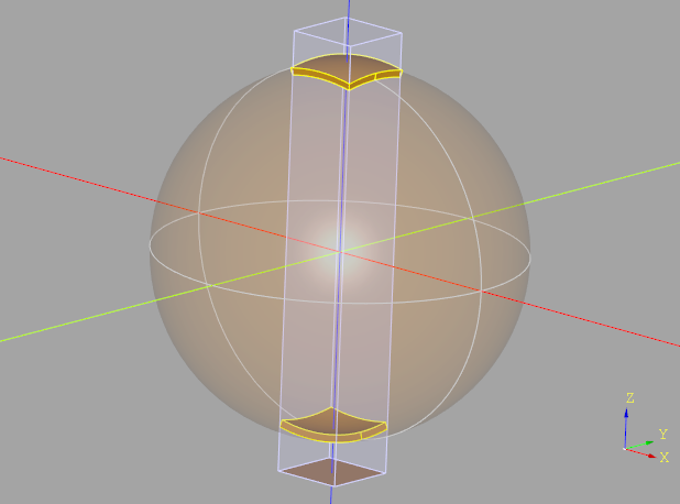
- projectToShape(targetObject, direction=None, center=None, internalFacePoints=[])
Project Face to target Object
Project a Face onto a Shape generating new Face(s) on the surfaces of the object one and only one of direction or center must be provided.
The two types of projections are illustrated below:
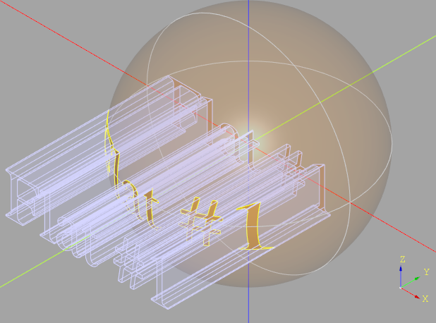
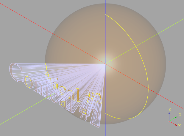
Note that an array of Faces is returned as the projection might result in faces on the “front” and “back” of the object (or even more if there are intermediate surfaces in the projection path). Faces “behind” the projection are not returned.
To help refine the resulting face, a list of planar points can be passed to augment the surface definition. For example, when projecting a circle onto a sphere, a circle will result which will get converted to a planar circle face. If no points are provided, a single center point will be generated and used for this purpose.
- Parameters
targetObject (
Shape) – Object to project ontodirection (
Optional[VectorLike]) – Parallel projection direction. Defaults to None.center (
Optional[VectorLike]) – Conical center of projection. Defaults to None.internalFacePoints (
list[Vector]) – Points refining shape. Defaults to [].
- Raises
ValueError – Only one of direction or center must be provided
- Return type
list[Face]- Returns
Face(s) projected on target object
- thicken(depth, direction=None)
Thicken Face
Create a solid from a potentially non planar face by thickening along the normals.
Non-planar faces are thickened both towards and away from the center of the sphere.
- Parameters
depth (
float) – Amount to thicken face(s), can be positive or negative.direction (
Optional[Vector]) – The direction vector can be used to indicate which way is ‘up’, potentially flipping the face normal direction such that many faces with different normals all go in the same direction (direction need only be +/- 90 degrees from the face normal). Defaults to None.
- Raises
RuntimeError – Opencascade internal failures
- Return type
Solid- Returns
The resulting Solid object
Location class extensions
Plane class extensions
Shape class extensions
- class Shape
-
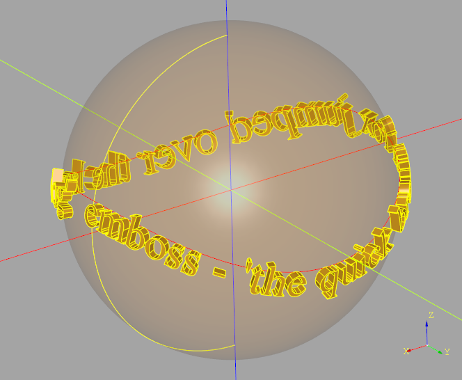
- embossText(txt, fontsize, depth, path, font='Arial', fontPath=None, kind='regular', valign='center', start=0, tolerance=0.1)
Embossed 3D text following the given path on Shape
Create 3D text by embossing each face of the planar text onto the shape along the path. If depth is not zero, the resulting face is thickened to the provided depth.
- Parameters
txt (
str) – Text to be renderedfontsize (
float) – Size of the font in model unitsdepth (
float) – Thickness of text, 0 returns a Face objectfont (
str) – Font name. Defaults to “Arial”.fontPath (
Optional[str]) – Path to font file. Defaults to None.kind (
Literal[‘regular’, ‘bold’, ‘italic’]) – Font type - one of “regular”, “bold”, “italic”. Defaults to “regular”.valign (
Literal[‘center’, ‘top’, ‘bottom’]) – Vertical Alignment - one of “center”, “top”, “bottom”. Defaults to “center”.start (
float) – Relative location on path to start the text. Defaults to 0.
- Return type
Compound- Returns
The embossed text
- findIntersection(point, direction)
Find point and normal at intersection
Return both the point(s) and normal(s) of the intersection of the line and the shape
- located(loc)
Apply a location in absolute sense to a copy of self
- makeFingerJointFaces(fingerJointEdges, materialThickness, targetFingerWidth, kerfWidth=0.0)
Extract Faces from the given Shape (Solid or Compound) and create Faces with finger joints cut into the given Edges.
- Parameters
self (Shape) – the base shape defining the finger jointed object
fingerJointEdges (list[Edge]) – the Edges to convert to finger joints
materialThickness (float) – thickness of the notch from edge
targetFingerWidth (float) – approximate with of notch - actual finger width will be calculated such that there are an integer number of fingers on Edge
kerfWidth (float, optional) – Extra size to add (or subtract) to account for the kerf of the laser cutter. Defaults to 0.0.
- Raises
ValueError – provide Edge is not shared by two Faces
- Returns
faces with finger joint cut into selected edges
- Return type
list[Face]
- maxFillet(edgeList, tolerance=0.1, maxIterations=10)
Find Maximum Fillet Size
Find the largest fillet radius for the given Shape and Edges with a recursive binary search.
- Parameters
edgeList (Iterable[Edge]) – a list of Edge objects, which must belong to this solid
tolerance (float, optional) – maximum error from actual value. Defaults to 0.1.
maxIterations (int, optional) – maximum number of recursive iterations. Defaults to 10.
- Raises
RuntimeError – failed to find the max value
ValueError – the provided Shape is invalid
- Returns
maximum fillet radius
- Return type
float
- As an example:
max_fillet_radius = my_shape.maxFillet(shape_edges)
- or:
max_fillet_radius = my_shape.maxFillet(shape_edges, tolerance=0.5, maxIterations=8)
- moved(loc)
Apply a location in relative sense (i.e. update current location) to a copy of self
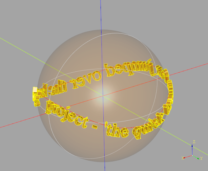
- projectText(txt, fontsize, depth, path, font='Arial', fontPath=None, kind='regular', valign='center', start=0)
Projected 3D text following the given path on Shape
Create 3D text using projection by positioning each face of the planar text normal to the shape along the path and projecting onto the surface. If depth is not zero, the resulting face is thickened to the provided depth.
Note that projection may result in text distortion depending on the shape at a position along the path.
- Parameters
txt (
str) – Text to be renderedfontsize (
float) – Size of the font in model unitsdepth (
float) – Thickness of text, 0 returns a Face objectfont (
str) – Font name. Defaults to “Arial”.fontPath (
Optional[str]) – Path to font file. Defaults to None.kind (
Literal[‘regular’, ‘bold’, ‘italic’]) – Font type - one of “regular”, “bold”, “italic”. Defaults to “regular”.valign (
Literal[‘center’, ‘top’, ‘bottom’]) – Vertical Alignment - one of “center”, “top”, “bottom”. Defaults to “center”.start (
float) – Relative location on path to start the text. Defaults to 0.
- Return type
Compound- Returns
The projected text
- transformed(rotate=(0, 0, 0), offset=(0, 0, 0))
Transform Shape
Rotate and translate the Shape by the three angles (in degrees) and offset. Functions exactly like the Workplane.transformed() method but for Shapes.
- Parameters
rotate (VectorLike, optional) – 3-tuple of angles to rotate, in degrees. Defaults to (0, 0, 0).
offset (VectorLike, optional) – 3-tuple to offset. Defaults to (0, 0, 0).
- Returns
transformed object
- Return type
Sketch class extensions
The Sketch extensions introduce a new way of specifying a point: a “snap” defined as “<tag>@<position>” which allows one to easily create features relative to previously tagged features.
- <tag>
<tag> refers to a previously defined tagged Edge or Wire.
- <position>
A float or int value between 0 and 1 which refers to a relative position along the object. A value of 0 (or 0.0) refers to the start of the Edge while 1 (or 1.0) refers to the end of the Edge. The middle of the Edge would be “my_edge@0.5”.
In addition to the numeric values, three string values can be used: start, middle, and end. For example: “perimeter@middle” will return the point half way along the previously tagged object perimeter.
Here is an example of using a pair of “snaps” to define a chord:
chord = (
        cq.Sketch()
        .center_arc(center=(0, 0), radius=10, start_angle=0, arc_size=60, tag="c")
        .polyline("c@1", "c@0")
        .assemble()
)
- class Sketch
- add(obj, angle=0, mode='a', tag=None)
Add a Wire, Edge or Face to this sketch
Examples:
added_edge = cq.Sketch().arc((50, 0), 50, 270, 270).add(external_edge).assemble()
- Parameters
- Return type
T- Returns
Updated sketch
- bounding_box(mode='a', tag=None)
Bounding Box
Create bounding box(s) around selected features. These bounding boxes can be used to directly construct shapes or to locate other shapes.
Examples:
mickey = (
    cq.Sketch()
    .circle(10)
    .faces()
    .bounding_box(tag="bb", mode="c")
    .faces(tag="bb")
    .vertices(">Y")
    .circle(7)
    .clean()
)

bounding_box_center = (
    cq.Sketch()
    .segment((0, 0), (10, 0))
    .segment((0, 5))
    .close()
    .assemble(tag="t")
    .faces(tag="t")
    .circle(0.5, mode="s")
    .faces(tag="t")
    .bounding_box(tag="bb", mode="c")
    .faces(tag="bb")
    .rect(1, 1, mode="s")
)

circles = (
    cq.Sketch()
    .rarray(40, 40, 2, 2)
    .circle(10)
    .reset()
    .faces()
    .bounding_box(tag="bb", mode="c")
    .vertices(tag="bb")
    .circle(7)
    .clean()
)
- Parameters
tag (Optional[str], optional) – feature label. Defaults to None.
- Return type
T- Returns
Updated sketch
- center_arc(center, radius, start_angle, arc_size, tag=None, for_construction=False)
Center Arc
A partial or complete circle with defined center
Examples:
chord = (
    cq.Sketch()
    .center_arc(center=(0, 0), radius=10, start_angle=0, arc_size=60, tag="c")
    .polyline("c@1", "c@0")
    .assemble()
)
- Parameters
center (Union[Point, str]) – point or snap defining the arc center
radius (float) – arc radius
start_angle (float) – in degrees, where zero corresponds to the +vs X axis
arc_size (float) – size of arc counter clockwise from start
tag (str, optional) – feature label. Defaults to None.
for_construction (bool, optional) – edge used to build other geometry. Defaults to False.
- Returns
Updated sketch
- mirror_x()
Mirror across X axis
Mirror the selected items across the X axis
- Raises
ValueError – Nothing selected
- Returns
Updated Sketch
- mirror_y()
Mirror across Y axis
Mirror the selected items across the Y axis
- Raises
ValueError – Nothing selected
- Returns
Updated Sketch
- polyline(*pts, tag=None, for_construction=False)
Polyline
A polyline defined by two or more points or snaps
Examples:
pline = cq.Sketch().polyline((0, 0), (1, 1), (2, 0), (3, 1), (4, 0))

triangle = (
    cq.Sketch()
    .polyline((0, 0), (2, 0), tag="base")
    .polyline("base@0", (1, 1), tag="left")
    .polyline("left@1", "base@1")
)
- Parameters
pts (Union[Point,str]) – sequence of points or snaps
tag (str, optional) – feature label. Defaults to None.
for_construction (bool, optional) – edge used to build other geometry. Defaults to False.
- Raises
ValueError – polyline requires two or more pts
- Returns
Updated sketch
- push_points(*pts, tag=None)
Select the provided points
Add the provided points, locations or snaps to current selections
Examples:
circles_on_arc = (
    cq.Sketch()
    .center_arc(center=(0, 0), radius=10, start_angle=0, arc_size=90, tag="c")
    .push_points("c@0.1", "c@0.5", "c@0.9")
    .circle(1)
)
- Parameters
pts (Union[Point,str,Location]) – points to add
tag (str, optional) – feature label. Defaults to None.
- Return type
T- Returns
Updated sketch
- snap_to_vector(pts, find_tangents=False)
Snap to Vector
Convert Snaps to Vector
- Parameters
pts (Union[Point,str]) – list of Snaps
find_tangents (bool) – return tangents instead of positions. Defaults to False.
- Returns
a list of Vectors possibly extracted from tagged objects
- Return type
list(Vector)
- spline(*pts, tangents=None, tangent_scalars=None, periodic=False, tag=None, for_construction=False)
Construct a spline
Examples:
boomerang = (
    cq.Sketch()
    .center_arc(center=(0, 0), radius=10, start_angle=0, arc_size=90, tag="c")
    .spline("c@1", (10, 10), "c@0", tangents=("c@1", "c@0"))
)
- Parameters
pts (Union[Point,str]) – sequence of points or snaps defining the spline
tangents (Iterable[Union[Point, str]], optional) – spline tangents or snaps. Defaults to None.
tangent_scalars (Iterable[float], optional) – tangent multipliers to refine the shape. Defaults to None.
periodic (bool, optional) – creation of periodic curves. Defaults to False.
tag (str, optional) – feature label. Defaults to None.
for_construction (bool, optional) – edge used to build other geometry. Defaults to False.
- Return type
T- Returns
Updated Sketch
- tangent_arc(*pts, tangent=None, tangent_from_first=True, tag=None, for_construction=False)
Tangent Arc
Create an arc defined by the provided points and a tangent
Examples:
tangent_arc = (
    cq.Sketch()
    .center_arc(center=(0, 0), radius=10, start_angle=0, arc_size=90, tag="c")
    .tangent_arc("c@0.5", (10, 10), tag="t")
)
- Parameters
pts (Union[Point,str]) – start and end point or snap of arc
tangent (Point, optional) – tangent value if snaps aren’t used. Defaults to None.
tangent_from_first (bool, optional) – using a value of False will build the arc in the reverse direction. Defaults to True.
tag (str, optional) – feature label. Defaults to None.
for_construction (bool, optional) – edge used to build other geometry. Defaults to False.
- Raises
ValueError – tangentArc requires two points
ValueError – no tangent provided
- Returns
Updated sketch
- text(txt, fontsize, font='Arial', font_path=None, font_style='regular', halign='left', valign='center', position_on_path=0.0, angle=0, mode='a', tag=None)
Text that optionally follows a path.
The text that is created can be combined as with other sketch features by specifying a mode or rotated by the given angle. In addition, the text will follow the path defined by edges that have been previously created with arc or segment. The positionOnPath parameter can be used to shift the text along the path to achieve precise positioning.
Examples:
simple_text = cq.Sketch().text("simple", 10, angle=10)

loop_sketch = (
    cq.Sketch()
        .arc((-50, 0), 50, 90, 270)
        .arc((50, 0), 50, 270, 270)
        .text("loop_" * 20, 10)
)
- Parameters
txt (
str) – text to be renderedfontsize (
float) – size of the font in model unitsfont (
str) – font namefont_path (
Optional[str]) – system path to font filefont_style (
Literal[‘regular’, ‘bold’, ‘italic’]) – one of [“regular”, “bold”, “italic”]. Defaults to “regular”.halign (
Literal[‘center’, ‘left’, ‘right’]) – horizontal alignment, one of [“center”, “left”, “right”]. Defaults to “left”.valign (
Literal[‘center’, ‘top’, ‘bottom’]) – vertical alignment, one of [“center”, “top”, “bottom”]. Defaults to “center”.position_on_path (
float) – the relative location on path to locate the text, between 0.0 and 1.0. Defaults to 0.0.angle (
float) – rotation angle. Defaults to 0.0.mode (
Literal[‘a’, ‘s’, ‘i’, ‘c’]) – combination mode, one of [“a”,”s”,”i”,”c”]. Defaults to “a”.tag (
Optional[str]) – feature label. Defaults to None.
- Return type
T- Returns
a Sketch object
- three_point_arc(*pts, tag=None, for_construction=False)
Three Point Arc
Construct an arc through a sequence of points or snaps
Examples:
three_point_arc = (
    cq.Sketch()
    .polyline((0, 10), (0, 0), (10, 0), tag="p")
    .three_point_arc("p@0", "p@0.5", "p@1")
)
- Parameters
pts (Union[Point,str]) – sequence of points or snaps
tag (str, optional) – feature label. Defaults to None.
for_construction (bool, optional) – edge used to build other geometry. Defaults to False.
- Raises
ValueError – three_point_arc requires three points
- Return type
T- Returns
Updated sketch
- val()
Return the first selected value
Examples:
edge_object = cq.Sketch().arc((-50, 0), 50, 90, 270).edges().val()
Vector class extensions
- class Vector
- getSignedAngle(v, normal=None)
Signed Angle Between Vectors
Return the signed angle in RADIANS between two vectors with the given normal based on this math: angle = atan2((Va × Vb) ⋅ Vn, Va ⋅ Vb)
- rotateX(angle)
Rotate Vector about X-Axis
- Parameters
angle (
float) – Angle in degrees- Return type
- Returns
Rotated Vector
- rotateY(angle)
Rotate Vector about Y-Axis
- Parameters
angle (
float) – Angle in degrees- Return type
- Returns
Rotated Vector
- rotateZ(angle)
Rotate Vector about Z-Axis
- Parameters
angle (
float) – Angle in degrees- Return type
- Returns
Rotated Vector
Vertex class extensions
- class Vertex
- __add__(other)
Add
Add to a Vertex with a Vertex, Vector or Tuple
- Parameters
other (
Union[Vertex,Vector,Tuple[float,float,float]]) – Value to add- Raises
TypeError – other not in [Tuple,Vector,Vertex]
- Return type
- Returns
Result
Example
part.faces(“>Z”).vertices(“<Y and <X”).val() + (0, 0, 15)
which creates a new Vertex 15mm above one extracted from a part. One can add or subtract a cadquery
Vertex,Vectorortupleof float values to a Vertex with the provided extensions.
- __str__()
Return str(self).
- __sub__(other)
Subtract
Substract a Vertex with a Vertex, Vector or Tuple from self
- Parameters
- Raises
TypeError – other not in [Tuple,Vector,Vertex]
- Return type
- Returns
Result
Example
part.faces(“>Z”).vertices(“<Y and <X”).val() - Vector(10, 0, 0)
Wire class extensions
- class Wire
- embossToShape(targetObject, surfacePoint, surfaceXDirection, tolerance=0.01)
Emboss Wire on target object
Emboss an Wire on the XY plane onto a Shape while maintaining original wire dimensions where possible.
The embossed wire can be used to build features as:
with the sweep() method.
- Parameters
targetObject (
Shape) – Object to emboss ontosurfacePoint (
VectorLike) – Point on target object to start embossingsurfaceXDirection (
VectorLike) – Direction of X-Axis on target objecttolerance (
float) – maximum allowed error in embossed wire length. Defaults to 0.01.
- Raises
RuntimeError – Embosses wire is invalid
- Return type
- Returns
Embossed wire
- makeNonPlanarFace(surfacePoints=None, interiorWires=None)
Create Non-Planar Face with perimeter Wire
Create a potentially non-planar face bounded by exterior Wire, optionally refined by surfacePoints with optional holes defined by interiorWires.
The surfacePoints parameter can be used to refine the resulting Face. If no points are provided a single central point will be used to help avoid the creation of a planar face.
- Parameters
surfacePoints (
Optional[list[Vector]]) – Points on the surface that refine the shape. Defaults to None.interiorWires (
Optional[list[Wire]]) – Hole(s) in the face. Defaults to None.
- Raises
RuntimeError – Opencascade core exceptions building face
- Return type
- Returns
Non planar face
- makeRect(height, center, normal, xDir=None)
Make Rectangle
Make a Rectangle centered on center with the given normal
- projectToShape(targetObject, direction=None, center=None)
Project Wire
Project a Wire onto a Shape generating new Wires on the surfaces of the object one and only one of direction or center must be provided. Note that one or more wires may be generated depending on the topology of the target object and location/direction of projection.
To avoid flipping the normal of a face built with the projected wire the orientation of the output wires are forced to be the same as self.
- Parameters
targetObject (
Shape) – Object to project ontodirection (
Optional[VectorLike]) – Parallel projection direction. Defaults to None.center (
Optional[VectorLike]) – Conical center of projection. Defaults to None.
- Raises
ValueError – Only one of direction or center must be provided
- Return type
list[Wire]- Returns
Projected wire(s)
- sortedEdges(tolerance=1e-05)
Edges sorted by position
Extract the edges from the wire and sort them such that the end of one edge is within tolerance of the start of the next edge
- Parameters
tolerance (float, optional) – Max separation between sequential edges. Defaults to 1e-5.
- Raises
ValueError – Wire is disjointed
- Returns
Edges sorted by position
- Return type
list(Edge)
Workplane class extensions
- class Workplane
- clearanceHole(fastener, washers=None, fit='Normal', depth=None, counterSunk=True, captiveNut=False, baseAssembly=None, clean=True)
Clearance Hole
Put a clearance hole in a shape at the provided location
For more information on how to use clearanceHole() see Custom Holes.
- Parameters
washers (
Optional[list[Washer]]) – A list of washer instances, can be emptyfit (
Optional[Literal[‘Close’, ‘Normal’, ‘Loose’]]) – one of “Close”, “Normal”, “Loose” which determines clearance hole diameter. Defaults to “Normal”.depth (
Optional[float]) – hole depth. Defaults to through part.counterSunk (
Optional[bool]) – Is the fastener countersunk into the part?. Defaults to True.baseAssembly (
Optional[Assembly]) – Assembly to add faster to. Defaults to None.clean (
Optional[bool]) – execute a clean operation remove extraneous internal features. Defaults to True.
- Raises
ValueError – clearanceHole doesn’t accept fasteners of type HeatSetNut - use insertHole instead
- Return type
T- Returns
the shape on the workplane stack with a new clearance hole
- fastenerHole(hole_diameters, fastener, washers, countersinkProfile, depth=None, fit=None, material=None, counterSunk=True, captiveNut=False, baseAssembly=None, hand=None, simple=False, clean=True)
Fastener Specific Hole
Makes a counterbore clearance, tap or threaded hole for the given screw for each item on the stack. The surface of the hole is at the current workplane.
- Parameters
hole_diameters (
dict) – either clearance or tap hole diameter specificationswashers (
list[Washer]) – A list of washer instances, can be emptycountersinkProfile (
Workplane) – the 2D side profile of the fastener (not including a screw’s shaft)depth (
Optional[float]) – hole depth. Defaults to through part.fit (
Optional[Literal[‘Close’, ‘Normal’, ‘Loose’]]) – one of “Close”, “Normal”, “Loose” which determines clearance hole diameter. Defaults to None.material (
Optional[Literal[‘Soft’, ‘Hard’]]) – on of “Soft”, “Hard” which determines tap hole size. Defaults to None.counterSunk (
Optional[bool]) – Is the fastener countersunk into the part?. Defaults to True.captiveNut (
Optional[bool]) – Countersink with a rectangular, filleted, hole. Defaults to False.baseAssembly (
Optional[Assembly]) – Assembly to add faster to. Defaults to None.hand (
Optional[Literal[‘right’, ‘left’]]) – tap hole twist direction either “right” or “left”. Defaults to None.simple (
Optional[bool]) – tap hole thread complexity selector. Defaults to False.clean (
Optional[bool]) – execute a clean operation remove extraneous internal features. Defaults to True.
- Raises
ValueError – fit or material not in hole_diameters dictionary
- Return type
T- Returns
the shape on the workplane stack with a new hole
- hexArray(diagonal, xCount, yCount, center=True)
Create Hex Array
Creates a hexagon array of points and pushes them onto the stack. If you want to position the array at another point, create another workplane that is shifted to the position you would like to use as a reference
- Parameters
diagonal (
float) – tip to tip size of hexagon ( must be > 0)xCount (
int) – number of points ( > 0 )yCount (
int) – number of points ( > 0 )center (
Union[bool,tuple[bool,bool]]) – If True, the array will be centered around the workplane center. If False, the lower corner will be on the reference point and the array will extend in the positive x and y directions. Can also use a 2-tuple to specify centering along each axis.
- Returns
Places points on the Workplane stack
- insertHole(fastener, fit='Normal', depth=None, baseAssembly=None, clean=True, manufacturingCompensation=0.0)
Insert Hole
Put a hole appropriate for an insert nut at the provided location
For more information on how to use insertHole() see Custom Holes.
- Parameters
fastener (
Nut) – An insert nut instancefit (
Optional[Literal[‘Close’, ‘Normal’, ‘Loose’]]) – one of “Close”, “Normal”, “Loose” which determines clearance hole diameter. Defaults to “Normal”.depth (
Optional[float]) – hole depth. Defaults to through part.baseAssembly (
Optional[Assembly]) – Assembly to add faster to. Defaults to None.clean (
Optional[bool]) – execute a clean operation remove extraneous internal features. Defaults to True.manufacturingCompensation (float, optional) – used to compensate for over-extrusion of 3D printers. A value of 0.2mm will reduce the radius of an external thread by 0.2mm (and increase the radius of an internal thread) such that the resulting 3D printed part matches the target dimensions. Defaults to 0.0.
- Raises
ValueError – insertHole only accepts fasteners of type HeatSetNut
- Return type
T- Returns
the shape on the workplane stack with a new clearance hole
- makeFingerJoints(materialThickness, targetFingerWidth, kerfWidth=0.0, baseAssembly=None)
Starting with a base object and a set of selected edges, create Faces with finger joints that they could be laser cut from flat material.
Example
For example, make a simple open topped laser cut box.
finger_jointed_box_assembly = Assembly()
finger_jointed_faces = (
    Workplane("XY")
    .box(100, 80, 60)
    .edges("not >Z")
    .makeFingerJoints(
        materialThickness=5,
        targetFingerWidth=10,
        kerfWidth=1,
        baseAssembly=finger_jointed_box_assembly,
    )
)
The assembly part is optional but if present the Assembly will contain the parts as if they were laser cut from a material of the given thickness.
- Parameters
self (T) – workplane
materialThickness (float) – thickness of finger joints
targetFingerWidth (float) – approximate with of notch - actual finger width will be calculated such that there are an integer number of fingers on Edge
kerfWidth (float, optional) – Extra size to add (or subtract) to account for the kerf of the laser cutter. Defaults to 0.0.
baseAssembly (Assembly, optional) – Assembly to add parts to
- Raises
ValueError – Missing Solid object
ValueError – Missing finger joint Edges
- Returns
Faces ready to be exported to DXF files and laser cut
- Return type
T
- pressFitHole(bearing, interference=0, fit='Normal', depth=None, baseAssembly=None, clean=True)
Press Fit Hole
Put a hole appropriate for a bearing at the provided location
For more information on how to use pressFitHole() see Custom Holes.
- Parameters
bearing (
Bearing) – A bearing instanceinterference (
float) – The amount the decrease the hole radius from the bearing outer radius. Defaults to 0.fit (
Optional[Literal[‘Close’, ‘Normal’, ‘Loose’]]) – one of “Close”, “Normal”, “Loose” which determines hole diameter for the bore. Defaults to “Normal”.depth (
Optional[float]) – hole depth. Defaults to through part.baseAssembly (
Optional[Assembly]) – Assembly to add faster to. Defaults to None.clean (
Optional[bool]) – execute a clean operation remove extraneous internal features. Defaults to True.
- Raises
ValueError – pressFitHole only accepts bearings of type Bearing
- Return type
T- Returns
the shape on the workplane stack with a new press fit hole
- pushFastenerLocations(fastener, baseAssembly, offset=0, flip=False)
Push Fastener Locations
Push the Location(s) of the given fastener relative to the given Assembly onto the workplane stack.
- Returns
Location objects on the workplane stack
- tapHole(fastener, washers=None, material='Soft', depth=None, counterSunk=True, fit='Normal', baseAssembly=None, clean=True)
Tap Hole
Put a tap hole in a shape at the provided location
For more information on how to use tapHole() see Custom Holes.
- Parameters
washers (
Optional[list[Washer]]) – A list of washer instances, can be emptymaterial (
Optional[Literal[‘Soft’, ‘Hard’]]) – on of “Soft”, “Hard” which determines tap hole size. Defaults to “Soft”.depth (
Optional[float]) – hole depth. Defaults to through part.counterSunk (
Optional[bool]) – Is the fastener countersunk into the part?. Defaults to True.fit (
Optional[Literal[‘Close’, ‘Normal’, ‘Loose’]]) – one of “Close”, “Normal”, “Loose” which determines clearance hole diameter. Defaults to None.baseAssembly (
Optional[Assembly]) – Assembly to add faster to. Defaults to None.clean (
Optional[bool]) – execute a clean operation remove extraneous internal features. Defaults to True.
- Raises
ValueError – tapHole doesn’t accept fasteners of type HeatSetNut - use insertHole instead
- Return type
T- Returns
the shape on the workplane stack with a new tap hole
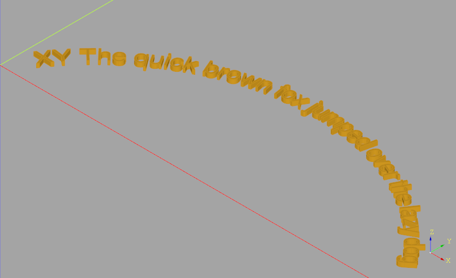
- textOnPath(txt, fontsize, distance, cut=True, combine=False, clean=True, font='Arial', fontPath=None, kind='regular', halign='left', valign='center', positionOnPath=0.0)
Returns 3D text with the baseline following the given path.
The parameters are largely the same as the Workplane.text() method. The start parameter (normally between 0.0 and 1.0) specify where on the path to start the text.
The path that the text follows is defined by the last Edge or Wire in the Workplane stack. Path’s defined outside of the Workplane can be used with the add(<path>) method.
- Parameters
txt (
str) – text to be renderedfontsize (
float) – size of the font in model unitsdistance (
float) – the distance to extrude or cut, normal to the workplane plane, negative means opposite the normal directioncut (
bool) – True to cut the resulting solid from the parent solids if foundcombine (
bool) – True to combine the resulting solid with parent solids if foundclean (
bool) – callclean()afterwards to have a clean shapefont (
str) – font namefontPath (
Optional[str]) – path to font filekind (
Literal[‘regular’, ‘bold’, ‘italic’]) – font stylehalign (
Literal[‘center’, ‘left’, ‘right’]) – horizontal alignmentvalign (
Literal[‘center’, ‘top’, ‘bottom’]) – vertical alignmentpositionOnPath (
float) – the relative location on path to position the text, values must be between 0.0 and 1.0
- Return type
T- Returns
a CQ object with the resulting solid selected
The returned object is always a Workplane object, and depends on whether combine is True, and whether a context solid is already defined:
if combine is False, the new value is pushed onto the stack.
if combine is true, the value is combined with the context solid if it exists, and the resulting solid becomes the new context solid.
Examples:
fox = (
    Workplane("XZ")
    .threePointArc((50, 30), (100, 0))
    .textOnPath(
        txt="The quick brown fox jumped over the lazy dog",
        fontsize=5,
        distance=1,
        start=0.1,
    )
)

clover = (
    Workplane("front")
    .moveTo(0, 10)
    .radiusArc((10, 0), 7.5)
    .radiusArc((0, -10), 7.5)
    .radiusArc((-10, 0), 7.5)
    .radiusArc((0, 10), 7.5)
    .consolidateWires()
    .textOnPath(
        txt=".x" * 102,
        fontsize=1,
        distance=1,
    )
)
- thicken(depth, direction=None)
Thicken Face
Find all of the faces on the stack and make them Solid objects by thickening along the normals.
- Parameters
depth (
float) – Amount to thicken face(s), can be positive or negative.direction (
Optional[Vector]) – The direction vector can be used to indicate which way is ‘up’, potentially flipping the face normal direction such that many faces with different normals all go in the same direction (direction need only be +/- 90 degrees from the face normal). Defaults to None.
- Returns
A set of new objects on the Workplane stack
- threadedHole(fastener, depth, washers=None, hand='right', simple=False, counterSunk=True, fit='Normal', baseAssembly=None, clean=True)
Threaded Hole
Put a threaded hole in a shape at the provided location
For more information on how to use threadedHole() see Custom Holes.
- Parameters
fastener (
Screw) – A nut or screw instancedepth (
float) – hole depth. Defaults to through part.washers (
Optional[list[Washer]]) – A list of washer instances, can be emptyhand (
Literal[‘right’, ‘left’]) – tap hole twist direction either “right” or “left”. Defaults to None.simple (Optional[bool], optional) – [description]. Defaults to False.
counterSunk (
Optional[bool]) – Is the fastener countersunk into the part?. Defaults to True.fit (
Optional[Literal[‘Close’, ‘Normal’, ‘Loose’]]) – one of “Close”, “Normal”, “Loose” which determines clearance hole diameter. Defaults to None.baseAssembly (
Optional[Assembly]) – Assembly to add faster to. Defaults to None.clean (
Optional[bool]) – execute a clean operation remove extraneous internal features. Defaults to True.
- Raises
ValueError – threadedHole doesn’t accept fasteners of type HeatSetNut - use insertHole instead
- Return type
T- Returns
the shape on the workplane stack with a new threaded hole