drafting - model-based definition
A class used to document cadquery designs by providing three methods that place the dimensions and notes right on the 3D model.
For example:
import cadquery as cq
from cq_warehouse.drafting import Draft

# Import an object to be dimensioned
mystery_object = cq.importers.importStep("mystery.step")

# Create drawing instance with appropriate settings
metric_drawing = Draft(decimal_precision=1)

# Create an extension line from corners of the part
length_dimension_line = metric_drawing.extension_line(
    object_edge=mystery_object.faces("<Z").vertices("<Y").vals(),
    offset=10.0,
    tolerance=(+0.2, -0.1),
)

if "show_object" in locals():
    show_object(mystery_object, name="mystery_object")
    show_object(length_dimension_line, name="length_dimension_line")
To illustrate some of the capabilities of the drafting package, a set of dimension lines, extension lines and callouts were applied to a CadQuery part with no prior knowledge of any of the dimensions:
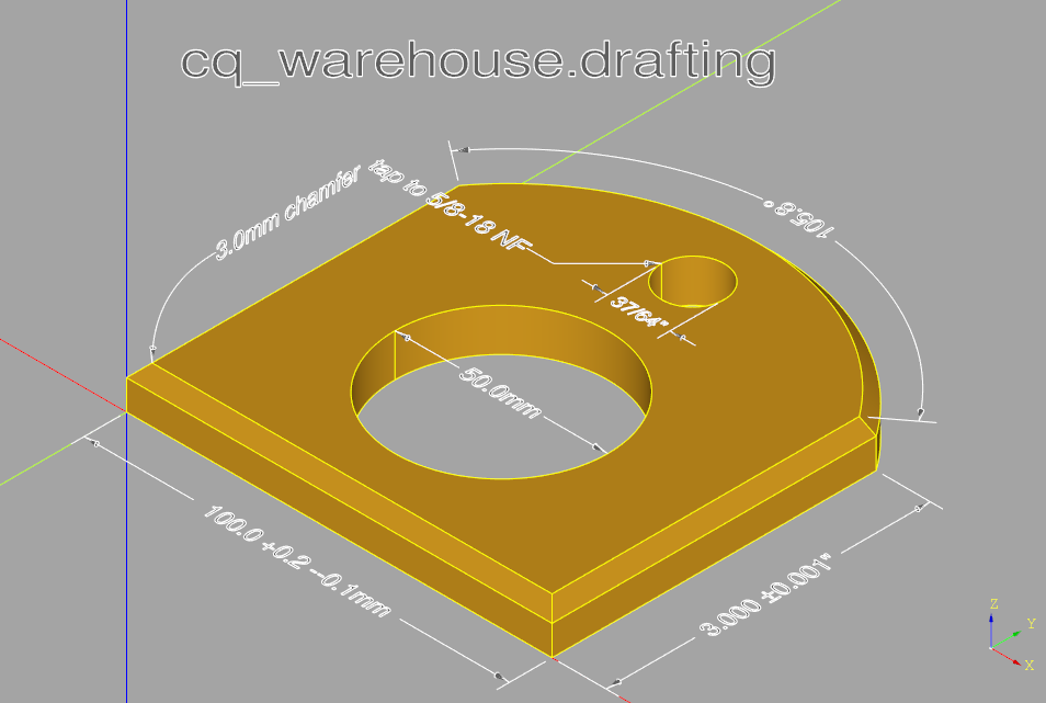
One could define three instances of the Draft class, one for each of the XY, XZ and YZ planes and generate a set of dimensions on each one. By enabling one of these planes at a time and exporting svg images traditional drafting documents can be generated.
When generating dimension lines there are three possibilities depending on the measurement and Draft attributes (described below):
The label text (possibly including units and tolerances) and arrows fit within the measurement,
The label text but not the arrows fit within the measurement, or
Neither the text nor the arrows fit within the measurements.
Cases 1 and 2 are shown in the above example. In case 3, the label will be attached to one of the external arrows.
These three possibilities are illustrated below with both linear and arc extension lines:
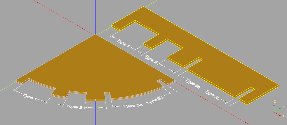
Note that type 3b can only be created by disabling the end arrow - see the arrows parameter below.
To help ease use, a new CadQuery type called PathDescriptor has been created which is defined as:
Union[Wire, Edge, list[Union[Vector, Vertex, tuple[float, float, float]]] i.e. a list of points or
CadQuery edge or wire either extracted from a part or created by the user.
The Draft class contains a set of attributes used to describe subsequent dimension_line(s), extension_line(s) or callout(s). The full list is as follows:
- class Draft(font_size=5.0, color=cadquery.Color, arrow_diameter=1.0, arrow_length=3.0, label_normal=None, units='metric', number_display='decimal', display_units=True, decimal_precision=2, fractional_precision=64, extension_gap=0)
Documenting cadquery designs with dimension and extension lines as well as callouts.
- Parameters
font_size (float) – size of the text in dimension lines and callouts. Defaults to 5.0.
color (Color, optional) – color of text, extension lines and arrows. Defaults to Color(0.25, 0.25, 0.25).
arrow_diameter (float) – maximum diameter of arrow heads. Defaults to 1.0.
arrow_length (float) – arrow head length. Defaults to 3.0.
label_normal (VectorLike, optional) – text and extension line plane normal. Defaults to XY plane.
units (Literal["metric", "imperial"]) – unit of measurement. Defaults to “metric”.
number_display (Literal["decimal", "fraction"]) – display numbers as decimals or fractions. Defaults to “decimal”.
display_units (bool) – control the display of units with numbers. Defaults to True.
decimal_precision (int) – number of decimal places when displaying numbers. Defaults to 2.
fractional_precision (int) – maximum fraction denominator - must be a factor of 2. Defaults to 64.
extension_gap (float) – gap between the point and start of extension line in extension_line.
Example
metric_drawing = Draft(decimal_precision=1)
length_dimension_line = metric_drawing.extension_line(
    object_edge=mystery_object.faces("<Z").vertices("<Y").vals(),
    offset=10.0,
    tolerance=(+0.2, -0.1),
)
The three public methods that the Draft class defines are described below. Note that both dimension_line ane extension_line support arcs as well as linear measurements - to be exact, the shown measurement is the length of the input path or object edge which could be an arbitrary shape like a spline. If this path or object_edge is part of a circle the size of the arc in degrees may be displayed instead of the length.
- callout(label, tail=None, origin=None, justify='left')
Callout
A text box with or without a tail pointing to another object used to provide extra information to the reader.
- Parameters
label (str) – the text to place within the callout - note that including a
\nin the text string will split the text over multiple lines.tail (Optional[PathDescriptor], optional) – an optional tail defined as above - note that if provided the text origin will be the start of the tail. Defaults to None.
origin (Optional[PointDescriptor], optional) – a very general definition of anchor point of the text defined as
PointDescriptor = Union[Vector, Vertex, Tuple[float, float, float]]Defaults to None.justify (Literal[, optional) – text alignment. Defaults to “left”.
- Raises
ValueError – Either origin or tail must be provided
- Returns
the callout
- Return type
- dimension_line(path, label=None, arrows=(True, True), tolerance=None, label_angle=False)
Dimension Line
Create a dimension line typically for internal measurements. Typically used for (but not restricted to) inside dimensions, a dimension line often as arrows on either side of a dimension or label.
There are three options depending on the size of the text and length of the dimension line: Type 1) The label and arrows fit within the length of the path Type 2) The text fit within the path and the arrows go outside Type 3) Neither the text nor the arrows fit within the path
- Parameters
path (PathDescriptor) – a very general type of input used to describe the path the dimension line will follow .
label (Optional[str], optional) – a text string which will replace the length (or arc length) that would otherwise be extracted from the provided path. Providing a label is useful when illustrating a parameterized input where the name of an argument is desired not an actual measurement. Defaults to None.
arrows (Tuple[bool, bool], optional) – a pair of boolean values controlling the placement of the start and end arrows. Defaults to (True, True).
tolerance (Optional[Union[float, Tuple[float, float]]], optional) – an optional tolerance value to add to the extracted length value. If a single tolerance value is provided it is shown as ± the provided value while a pair of values are shown as separate + and - values. Defaults to None.
label_angle (bool, optional) – a flag indicating that instead of an extracted length value, the size of the circular arc extracted from the path should be displayed in degrees.
- Raises
ValueError – No output - insufficient space for labels and no arrows selected
- Returns
the dimension line
- Return type
- extension_line(object_edge, offset, label=None, arrows=(True, True), tolerance=None, label_angle=False, project_line=None)
Extension Line
Create a dimension line with two lines extending outward from the part to dimension. Typically used for (but not restricted to) outside dimensions, with a pair of lines extending from the edge of a part to a dimension line.
- Parameters
object_edge (PathDescriptor) – a very general type of input defining the object to be dimensioned. Typically this value would be extracted from the part but is not restricted to this use.
offset (float) – a distance to displace the dimension line from the edge of the object
label (str, optional) – a text string which will replace the length (or arc length) that would otherwise be extracted from the provided path. Providing a label is useful when illustrating a parameterized input where the name of an argument is desired not an actual measurement. Defaults to None.
arrows (Tuple[bool, bool], optional) – a pair of boolean values controlling the placement of the start and end arrows. Defaults to (True, True).
tolerance (Optional[Union[float, Tuple[float, float]]], optional) – an optional tolerance value to add to the extracted length value. If a single tolerance value is provided it is shown as ± the provided value while a pair of values are shown as separate + and - values. Defaults to None.
label_angle (bool, optional) – a flag indicating that instead of an extracted length value, the size of the circular arc extracted from the path should be displayed in degrees. Defaults to False.
project_line (Vector, optional) – Vector line which to project dimension against.
- Returns
the extension line
- Return type